How we leverage ray marching to achieve visuals that would previously have been too complex to create, or too intense to use.
Rasterisation
When creating a complete, visual, 3D scene, there are a few common ways of doing so. Most commonly used is a system known as ‘Rasterisation.’ This takes a scene created out of pre-made shapes and textures, and figures out exactly what each pixel on your screen should look like. It cuts each object up into the pixel grid on your screen and uses the colour and shade of that object.
An example of rasterisation. This includes no anti-aliasing, so any pixel whose centre ‘x’ isn’t covered remains white.
This is very performant and gives artists a lot of control over exactly what they show to the end user. However, this means the computer has to figure out how an arbitrary shape might look. For example, it must consider shadows, ambient occlusion and reflections before it can overlay them. It must also consider each polygon (a flat surface on a 3D model, visibly divided in the above animation), meaning that extremely detailed models can cause performance issues.
Ray tracing
The other two primary techniques — ray tracing and ray marching — align much more closely with how the real world works. They tend to have a much more consistent performance, albeit at a higher initial performance cost. Both shoot out a ‘ray’ from each screen pixel and collect information from the surfaces they hit or bounce off of. If they miss an object, they can also easily trace back to nearby light sources to see how shadowed a specific pixel should be.
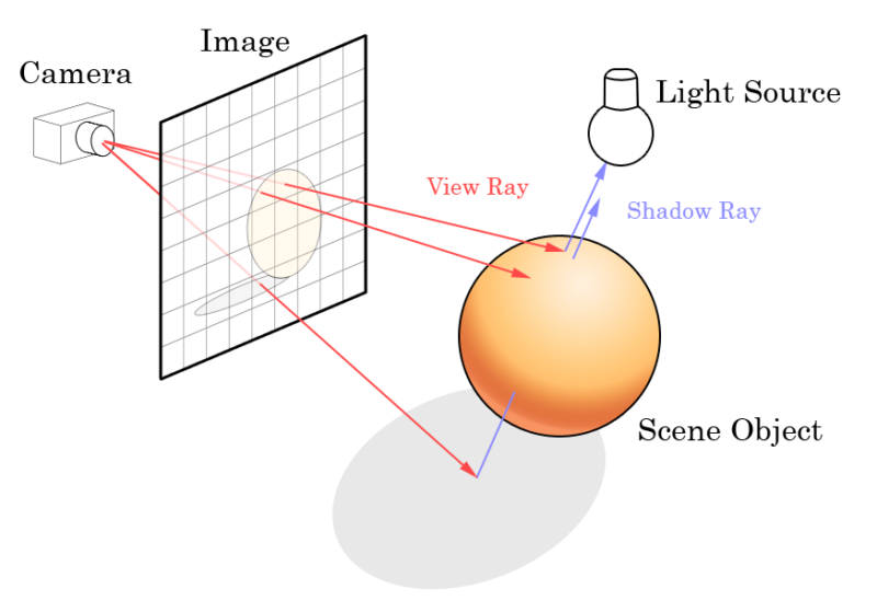
A demonstration of ray tracing. Each pixel on the screen is tested to calculate the final colour. Source: https://en.wikipedia.org/wiki/File:Ray_trace_diagram.png
While ray tracing also takes full advantage of artist-authored models, this means large numbers of repeating objects face similar challenges as in rasterisation. The computer must consider each object, and its surface detail can be a large contributor to the performance. Although there are ways to optimise this process, it is renowned for the realistic, but computationally intensive pictures it creates.
Ray marching
This brings us to our third rendering method, and the principal topic for this post: ray marching. It involves a similar process to ray tracing and considers each screen pixel independently. However, with this process, we stop before we hit an object and test how far away the nearest object is. This repeats until we’re extremely close to an object, or we’ve missed them entirely.
A demonstration of ray marching. Note how each next point is on the edge of the previous point’s circle. This lets us be confident that the next point we test will be outside of any objects without having to check every object.
The magic comes from how ray marching calculates the distance to the nearest object. This is where ‘Signed Distance Functions’ (SDFs) come in. While they’re worth a blog post in their own right, for this post you can think of them like a halo of numbers floating around each object. Each with a record of how far they are from the object.
Mathematics
So, as we march along our ray we can collect these numbers wherever we stop, making sure to find and keep track of the smallest value we’ve seen along the way. If this value gets really close to 0, we can assume we’ve hit something and colour the pixel accordingly.
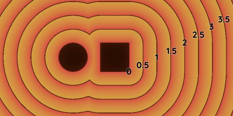
A visual representation of a Signed Distance Function (SDF). Notice how, close to both the circle and the square, we use the closest distance out of the two.
This means, however, that all the shapes in our scene have to be described mathematically. This means rather than designing arbitrary shapes with a 3D modelling program, we instead have to build our scenes out of these geometric, basic, shapes.
An example of moving SDFs, and using them to combine or cut-away from other shapes
These shapes can be more interesting than boxes and balls, however. Cones, donuts, capsules, and even fractal shapes are easy to create SDFs for. We’ll cover one of the more interesting results of this mathematical view of the digital world later.
Lighting
While this works great for colourful 2D visualisations, it isn’t very hard to take this same maths and extend it into the 3rd dimension. If we include some basic lighting and shading to give the scene some depth, we can create a convincing 3D scene. It can have complex geometry and moving parts with little extra effort or performance cost.
Pushing this further, we can even smooth the edges between each shape, creating gentle contours and smoothly merging each object. Once you combine many of these individual operations, you can create incredible, volumetric visualisations.
A 3D reconstruction of the 2D SDF. This one is composed of two spheres and a cube, and lit simply by a single light. The smooth blending of the shapes is being slowly changed, resulting in a number of unique visuals.
Shadows
At this point, we can discuss some of the biggest benefits of ray marching. Complex shadows, ambient occlusion, and repeated shapes are almost entirely ‘free’ in terms of performance cost. This is because we’ve collected all the information we need to calculate them already.
Ambient occlusion — the contact shadows made in crevices and corners — usually require complex calculations to determine how exposed a point is to ambient lighting. However, we can approximate this incredibly easily. When we’re marching along our ray, we’re already collecting information about how large an empty space surrounds it. When we hit, we can consider how small a space we had to squeeze into. This gives us a lot of estimations about how exposed our end ‘hit’ point is, and we darken it accordingly.
Penumbra
Shadows are also almost completely free. However, we have to do some work to figure out exactly how illuminated they should be. Once we’ve completed our ray march and hit an object, we can then march back towards the light source again. All the while collecting information on how close we are to the object. If we hit the object again, we’re in full shadow, but if we continue past and approach the light source, we know we’re in the soft penumbra region. We can then darken the pixel based on how close we came to an object. It’s simple, but very powerful, and produces some lovely shadows.
Shapes
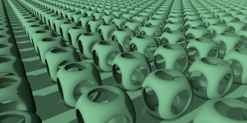
Now that we have a nicely lit scene, we can start experimenting with new shapes and repetitions. If we take the sampled positions from our ray march, we can loop our position, so that the calculations think they’re always close to the centre of the 3D scene. This lets us increase the amount of visual geometry without increasing the amount of work done, meaning it is essentially free, in terms of performance, to do so. This has a great application for background dressing, such as a repeating city skybox or for ground clutter.
Applications
Now we have an endless scene of shapes, we can convert them to something more interesting. There is an advantage of analytical rendering — using maths rather than predefined shapes and assets. We can produce shapes that would be impossible, or very difficult, to replicate with traditional 3D modelling software. For instance, we can create fractal geometry that would cause many performance problems in other rendering methods.
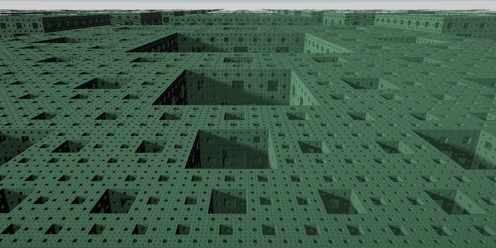
Infinitely tiled Menger sponges; a fractal visual that would be nearly impossible to achieve with other rendering methods given the level of detail present, especially with complex, soft, shadows.
A Mandelbrot 3D fractal. Analytical rendering means we only calculate geometry we’ll display and we can change the parameters of the calculation over time.
With these tools we can generate distant city scapes, interesting level geometry, and quirky visuals. There’s still work to be done, for instance, mapping a texture onto the 3D visuals. However, ray marching enables us to create complex and realistic visuals that were not possible before.